PCB for Manual and Autonomous Robots
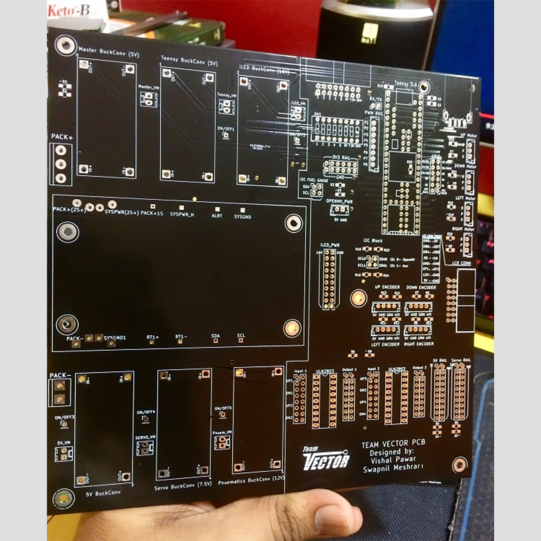
Image 1: PCB for Manual and Autonomous Robots (Top Side)
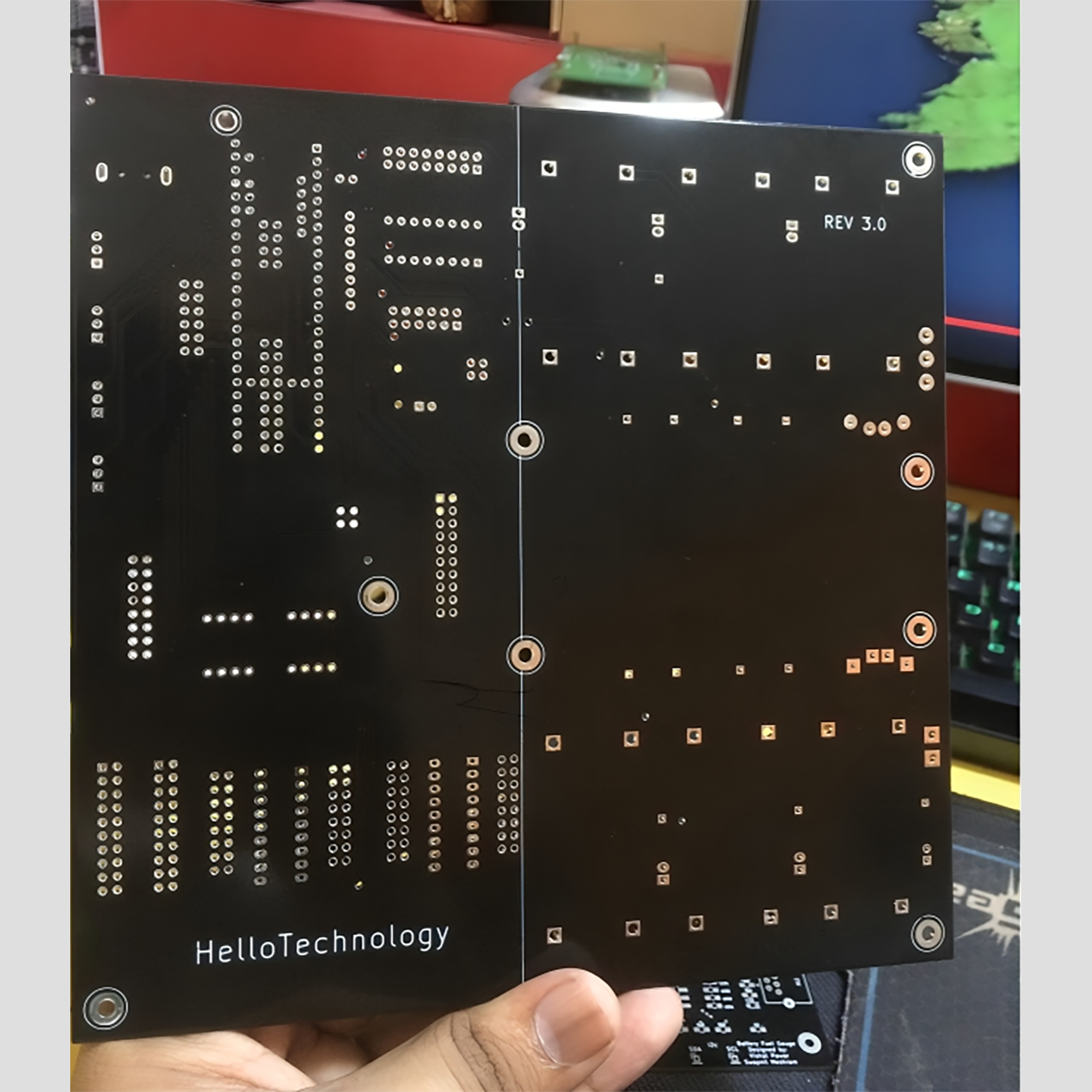
Image 2: PCB for Manual and Autonomous Robots (Bottom Side)
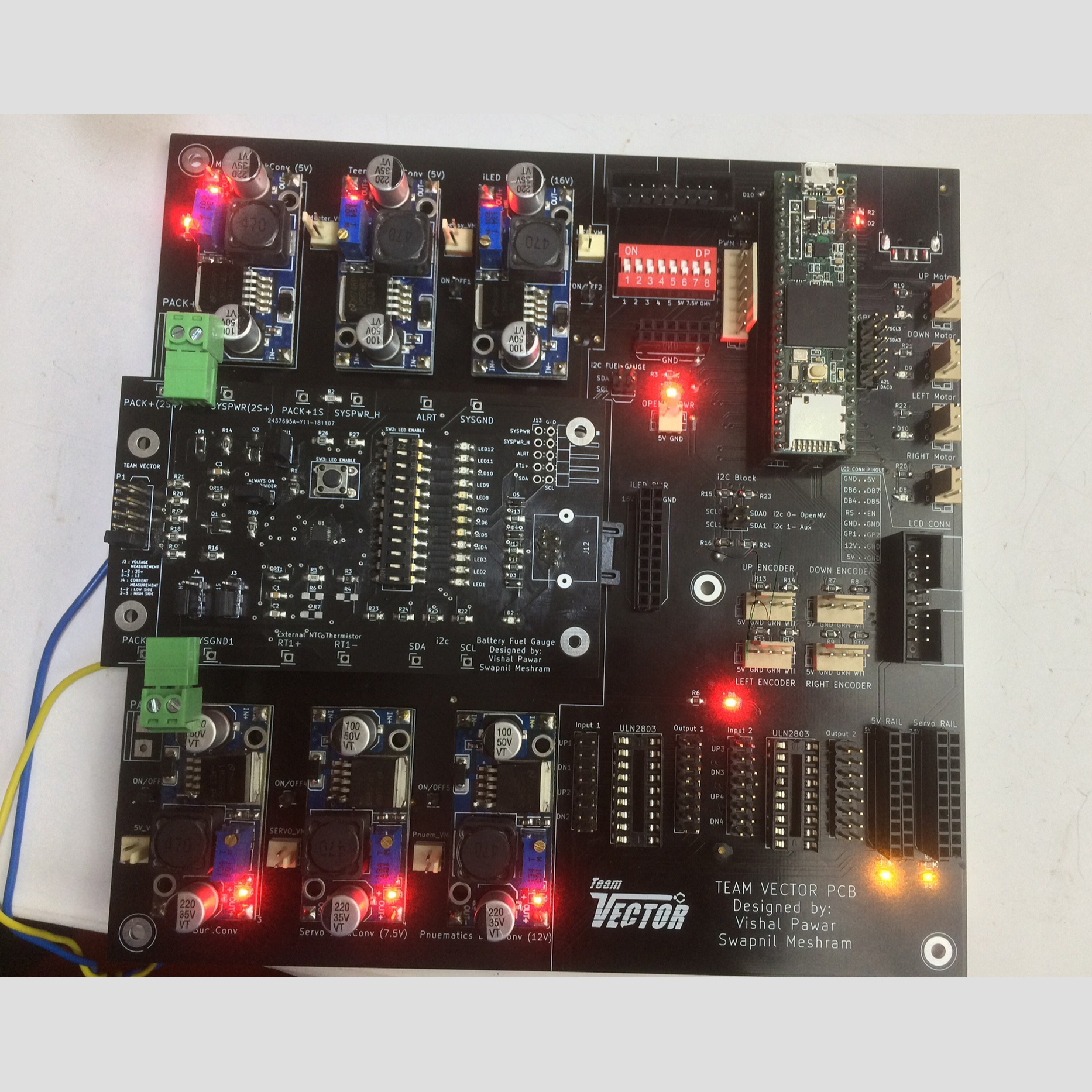
Image 3: PCB for Manual and Autonomous Robots (Assembled & Tested)
This is a double-layered PCB that works seamlessly with both manual and autonomous robots. One of the standout features of this project is the master/slave configuration for buck converters, which allows smooth activation and deactivation of slave buck converters from the master buck converter as needed. This strategic setup ensures efficient power distribution and optimization.
The PCB has a versatile power conditioning mechanism that operates across multiple voltage levels, thanks to the integration of buck and boost converter modules. Additionally, it boasts an array of sensor and actuator interfaces that allow for seamless interaction with various components.
Functionality-wise, the PCB is packed with an impressive range of features, including a Serial port, USB port, PWM channel, I2C block, a dedicated 12-pin GPIO with integrated ADC and DAC, an LCD connector, pneumatic control, and dedicated ports designed to accommodate rotary optical encoders, which provide essential and precise feedback mechanisms.
A defining highlight of this project is the incorporation of a customized 'Battery Fuel Gauge' system. This system effectively monitors single-cell or multi-cell lithium battery packs, seamlessly combining functionality and innovation.