PCB for Line Follower Robot
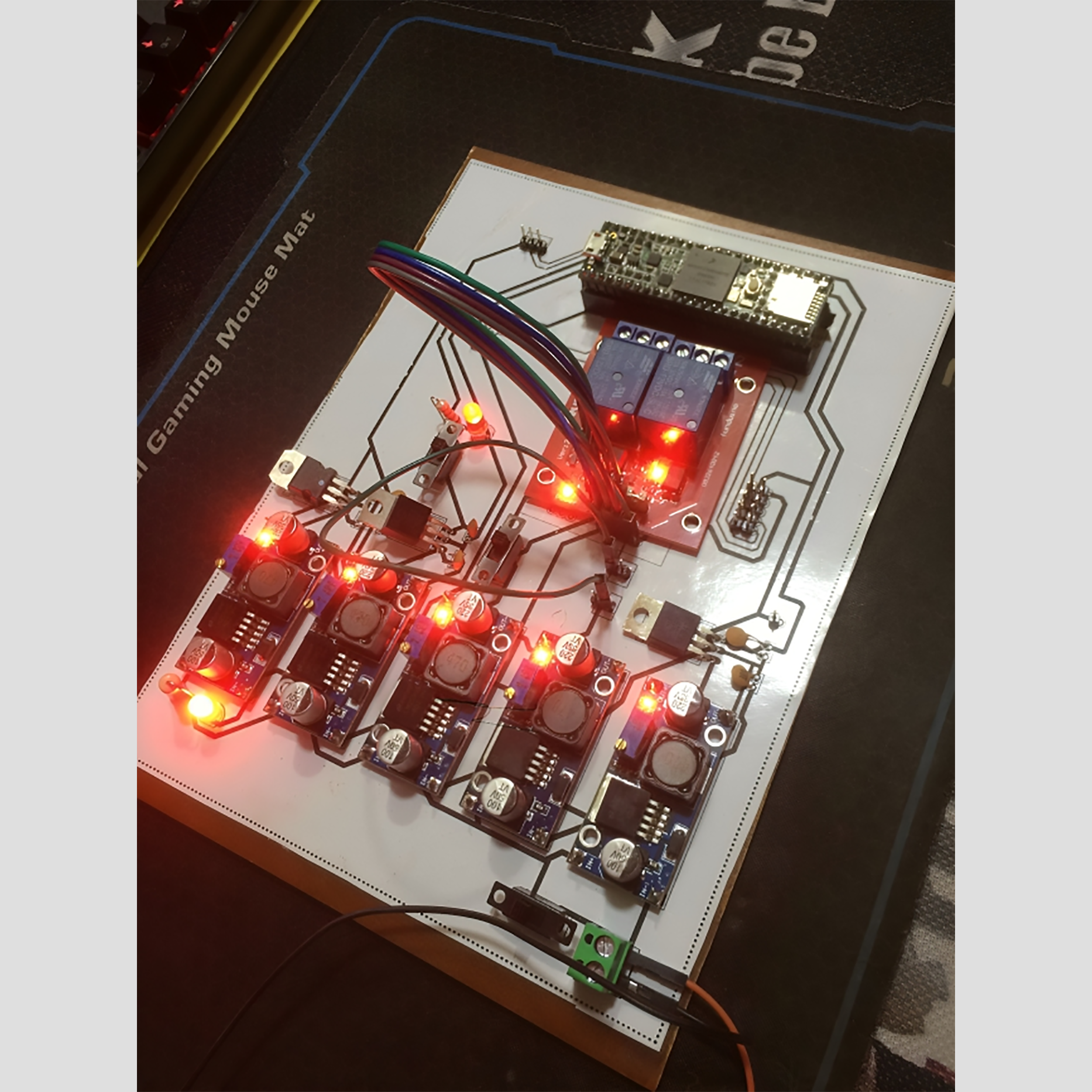
Image 1: PCB for Line Follower Robot (Assembled & Tested)
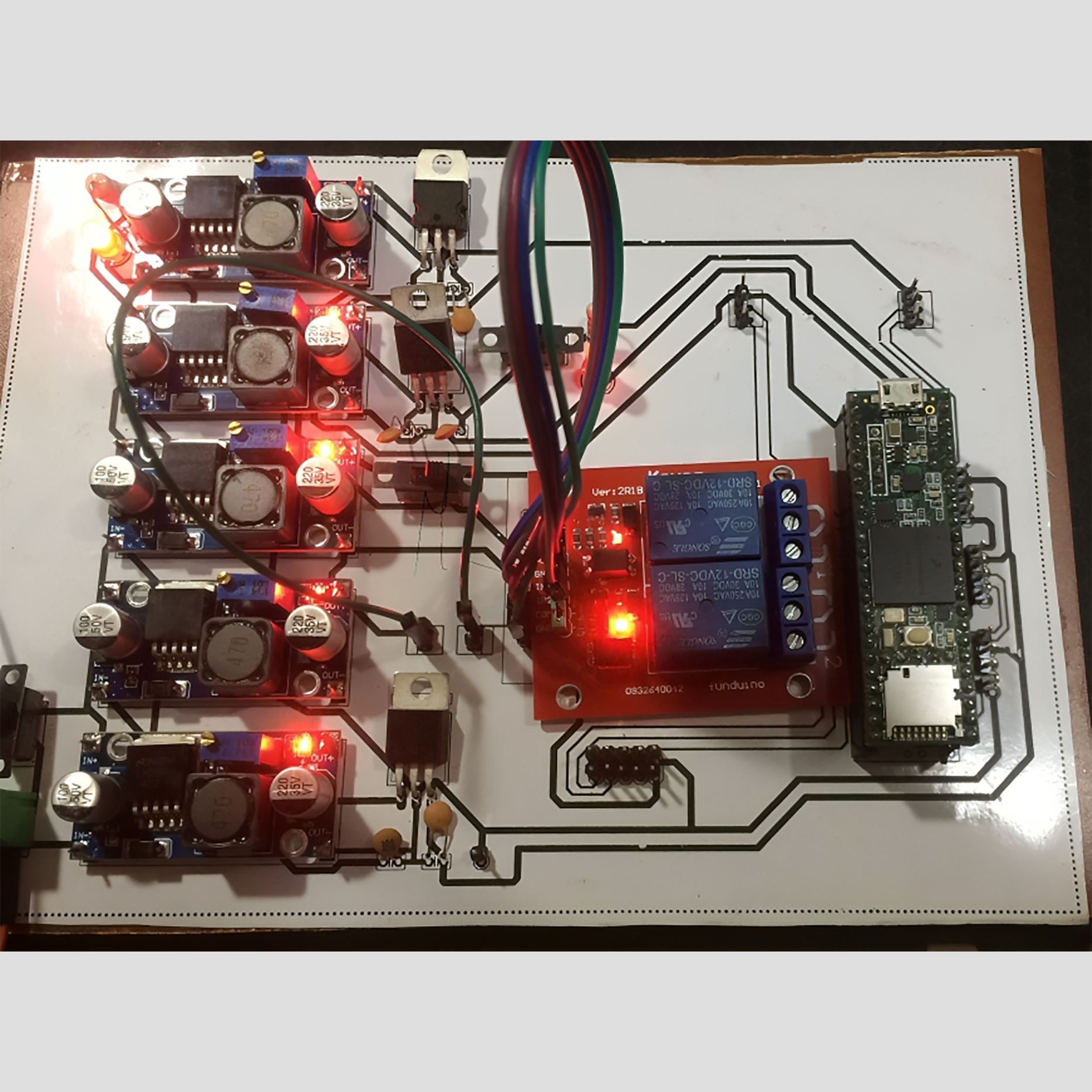
Image 2: PCB for Line Follower Robot (Assembled & Tested)
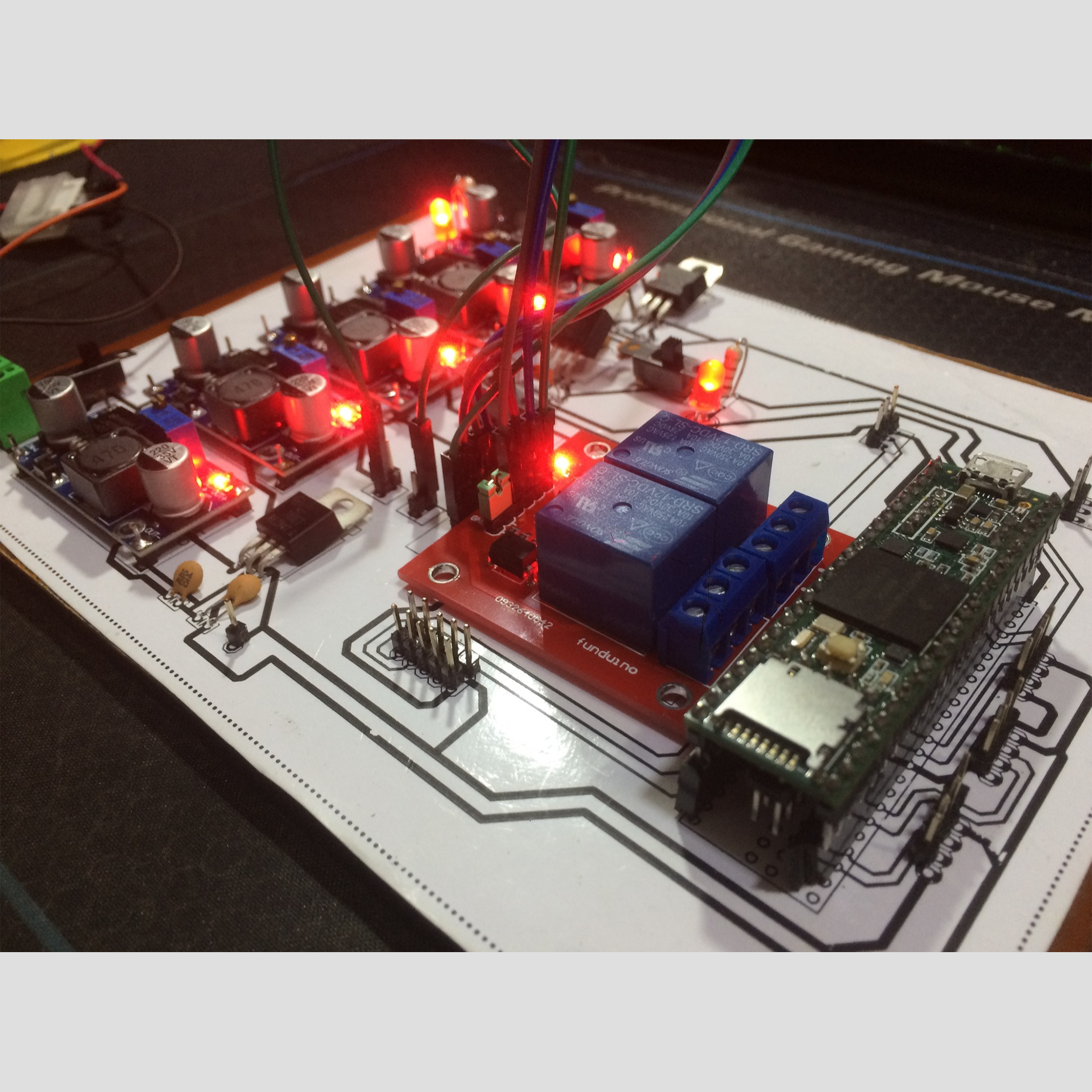
Image 3: PCB for Line Follower Robot (Assembled & Tested)
This project involved the design and development of a single-layer PCB that served as the foundation for the "PCB for Manual and Autonomous Robots." The board was designed to support both obstacle avoidance and path-following tasks, with a power-conditioning system that included fixed and variable voltage regulators for different voltage requirements.
The PCB provided interfaces for various sensors and actuators, including the Advanced Auto-Calibrating Line Sensor (LSA-08), obstacle-avoidance sensors, and motor interfaces. It also included a relay-based kill switch connected to a mushroom pushbutton, allowing the robot to be shut down when required.
The board was designed to integrate with different drive systems, providing the necessary power and control interfaces for robot movement across different applications.